Why do solar telecom integrated cabinets need to measure current
These measurements enable technicians to assess the system performance and better identify potential hazards. Imagine managing a telecom cabinet in a remote area where reliable grid power does not exist. The presence of direct current (DC) and alternating current (AC) in PV. th their business needs. As Architects of ContinuityTM, Vertiv solves the most important challenges facing today's data centers, communication networks and commercial and industrial facilities with a portfolio of power, cooling and IT infrastructure solutions and services that extends from the. Perhaps because an indoor photovoltaic energy cabinet is discreetly stationed inside a telecom outpost nearby. Offers continuous power supply to communication base stations—even during outages. Versatile capacity models from 10kWh to 40kWh to. [PDF Version]FAQs about Why do solar telecom integrated cabinets need to measure current
Why do solar panels need current sensors?
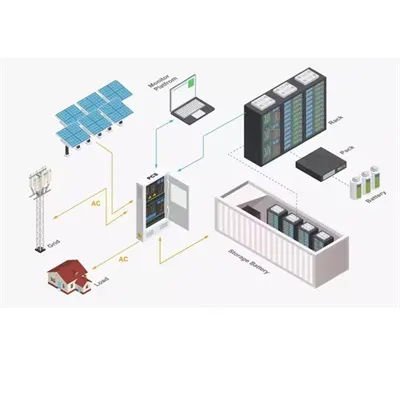
Current sensors are needed throughout grid-tied systems for control of the converters and inverters, optimization of power extraction from solar panels, and fault detection for safety. PV systems For a grid-tied photovoltaic system, the conversion of energy from solar panels is usually done in two stages.
Can solar power be used at telecom sites?
proves power harvesting. By leveraging the solar power at telecom sites, operators can substantially reduce th to -48VDC power system 2 kup system among othersLarge space for flexible application: the user equipment and battery chamber can share the same space, which can be flexibly adjusted based
Which energy solutions are suitable for telecom applications?
d financial performanceVertiv's Off-Grid Energy Solutions are suitable for telecom applications – from microwave repeaters to larg s Of-Grid Solar SolutionVertiv's of-grid solar solution ofers a complete energy portfolio that provides reliable and eficient telecom service, supporting remote areas where grid access is not feasible and fue
How does a grid-tied photovoltaic system work?
PV systems For a grid-tied photovoltaic system, the conversion of energy from solar panels is usually done in two stages. First, a DC / DC converter is used both to convert the voltage from the panel or array to something close to the grid voltage, as well as to maximize the power extracted from the panels.
.
What are the weak current solar telecom integrated cabinets
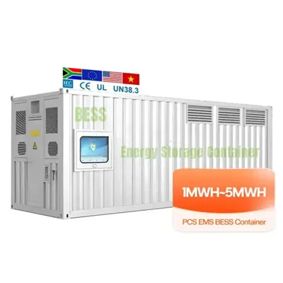
Integrates solar input, battery storage, and AC output in a compact single cabinet. Offers continuous power supply to communication base stations—even during outages. MPPT+solar modules deliver stable, efficient, and cost-effective power for telecom cabinets facing grid fluctuation or remote supply challenges. Operational costs drop by nearly 50% when switching from diesel generators. th their business needs. As Architects of ContinuityTM, Vertiv solves the most important challenges facing today's data centers, communication networks and commercial and industrial facilities with a portfolio of power, cooling and IT infrastructure solutions and services that extends from the. This is where energy-efficient outdoor telecom cabinets come in, playing a vital role in reducing energy use while maintaining high reliability and performance standards. By incorporating advanced cooling, intelligent monitoring, and efficient power systems, modern cabinets allow network operators. Perhaps because an indoor photovoltaic energy cabinet is discreetly stationed inside a telecom outpost nearby. Remote diagnosis, performance tracking, and fault alerts through intelligent BMS. [PDF Version]FAQs about What are the weak current solar telecom integrated cabinets
Which energy solutions are suitable for telecom applications?
d financial performanceVertiv's Off-Grid Energy Solutions are suitable for telecom applications – from microwave repeaters to larg s Of-Grid Solar SolutionVertiv's of-grid solar solution ofers a complete energy portfolio that provides reliable and eficient telecom service, supporting remote areas where grid access is not feasible and fue
Can solar power be used at telecom sites?
proves power harvesting. By leveraging the solar power at telecom sites, operators can substantially reduce th to -48VDC power system 2 kup system among othersLarge space for flexible application: the user equipment and battery chamber can share the same space, which can be flexibly adjusted based
Why are telecom providers expanding in remote regions?
ng reliable performance.To serve this growing demand for connectivity, telecom providers are now expanding, more than ever, in remote regions, on Top of Telecom TrendsIn this environment, where conventional energy sources are becoming more expensive, there is a growing opportunity to make
What is the STC of a solar panel?
na Solar Energy Co, Ltd. All reported values reflect STC: 1000W/ m2 Cell Temperature 25°C. Performance values for panels that are planned and un lution from 2kW to 24K ctices and installationEficient Arrangement defined to minimise losses associated with shadows, walls, fenc
.
What are the current measurements for solar-powered communication cabinets
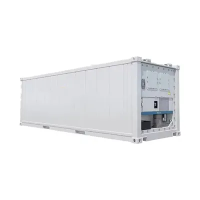
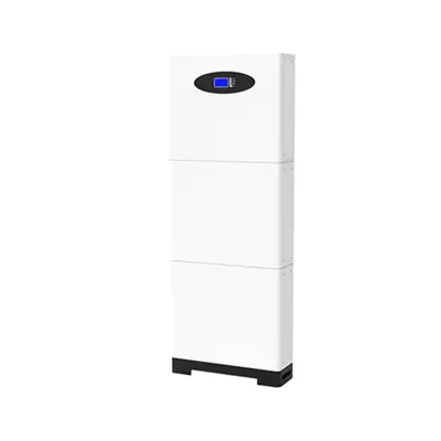
These cabinets typically draw between 30W and 60W, resulting in daily energy needs of 720Wh to 1,440Wh. Under optimal sunlight, a 100W panel can generate about 400Wh to 600Wh per day, depending on location and weather. The system's reliability depends on advanced power management. Technical managers often choose 100W modules for low-load sites, 200W modules for medium-load environments, and 300W modules for cabinets with higher energy needs. Choose solar. Discover how much an outdoor telecom cabinet costs in 2025, what factors affect pricing, and how features like weatherproofing, batteries, and solar integrat. Offers continuous power supply to communication base stations—even during outages. Versatile capacity models from 10kWh to 40kWh to. The Hybrid Solar Power System for Outdoor Cabinets combines solar photovoltaic panels with battery energy storage and optional backup power sources to provide reliable, continuous power for remote outdoor equipment enclosures. Designed to withstand harsh weather conditions, the system integrates. Your solar setup is a premium sunlamp without a telecom battery cabinet. [PDF Version]FAQs about What are the current measurements for solar-powered communication cabinets
How thick should a solar panel cable be?
For example, cables of 8 AWG thickness should be used for a parallel connected system using 40 A. These guidelines enable proper planning of the solar panel connections, allowing your solar energy system to operate more efficiently, with fewer energy losses, and for a longer duration. Which Solar Panel Wiring Method Is Right for You?
Why should you choose a solar power module?
In addition to our superior protection features, they are equipped with a solar panel and powerful backup battery that offer an uninterrupted power supply to small electronic devices. Our solar power modules are pre-built, easy to install, and scalable to fit operational requirements.
What is a solar panel wiring configuration?
A: Solar panel wiring configurations can be either set in series or parallel. When the solar system is connected in a series configuration, the voltage increases as the positive terminal of one solar panel is attached to the negative terminal of another solar panel.
What is a rated solar panel output?
The towers of a solar panel output, including current, voltage, and wattage, output is crucial in devising the best possible wiring schemes. In most cases, solar panels have what is called a rated output which specifies how the solar panels operate within Standard Test Conditions (STC).
.
Which is better for 600mm deep lead-acid battery cabinets used in field operations
Metal cabinets are generally more durable than plastic ones. They often wear out first with frequent use. These finishes make the cabinet look better and. Structural Containment: A well-designed rack supports the considerable weight of the batteries (especially lead-acid) without deforming, preventing collapses. Electrical Insulation: Materials and coatings must prevent accidental short circuits between battery terminals and the rack structure. While lithium batteries offer high energy density and excellent performance, their chemistry also makes them sensitive to temperature fluctuations, physical damage. Read on to learn how to choose the best battery cabinet. Battery technology Vented lead-acid (VLA) (frequently referred to as “flooded” or “wet cell”) batteries, which. [PDF Version]FAQs about Which is better for 600mm deep lead-acid battery cabinets used in field operations
What should a battery cabinet have?
Handles – provides an easy way to handle the battery cabinet. Battery holding brackets – they ensure the battery is always in a fixed position (no movement). Cooling plates – some have cooling plates that help to control the enclosure temperature. Insulation system – insulation is also a safety measure a battery cabinet should have.
Are battery cabinets safe?
Authorized personnel must be trained in battery safety. Battery cabinets must enclose the batteries behind locked doors accessible only to authorized personnel. As long as the cabinets are kept locked, they can be located in a computer room or other rooms accessible by non-battery technicians.
Which accumulator batteries are included in the cabinets covered by the technical specification?
The cabinets covered by the technical specification have been designed to contain the hermetic lead-acid electric accumulator batteries.
How to install a battery storage cabinet?
Mounting mechanism – they vary depending on whether the battery storage cabinet is a pole mount, wall mount, or floor mount. The mechanism allows you to install the battery box enclosure appropriately. Racks – these systems support batteries in the enclosure. Ideally, the battery rack should be strong.
.